+1 (317) 804-2330 | info@ballsystems.com | Blog

A multi-national, automotive supplier required a new, scalable alternator test system with open architecture, best in class Commercial Off the Shelf (COTS) components, and the ability to test more than 125 models, up to 18,000 RPM and up to a 500A load.
The solution was to create a scalable, custom designed, built, and validated alternator end-of-line manufacturing tester using National Instruments LabVIEW and TestStand software and Commercial Off the Shelf (COTS) components.
Our customer is a multi-national, automotive supplier with a location in central Indiana. They produce components for the automotive industry including light and heavy-duty alternators. Their previous test platform for their light and heavy-duty alternators eventually became obsolete because the platform was unmaintainable. The customer couldn’t make any adjustments to the tester, as alternators and technology advanced over time, without expensive and time-consuming engagement by the original system designer who owned the system IP.
The tester became an unacceptable business risk for our customer as they were trapped by a sole source provider that had high costs associated to hardware or software modifications, technology upgrades and the general repair and spare part replacement of their current system.
Ball Systems was selected to create a new, custom, open-architecture alternator tester based on our expertise in open system design and our promise to deliver all source documents to our customers.
The system designed by Ball Systems’ software, mechanical and electrical engineers is capable of testing both legacy DUT models (more than 125 different alternators) and scalable to address new alternator models across a wide and expanding array of testing requirements. The customer required that the source code would be provided, so their team can modify the test sequences in the future as needed.
In addition to the implementation of an open, scalable software architecture, the Ball Systems team designed, built and validated the alternator end-of-line manufacturing tester. The tester designed has universal mounting and fixturing scheme by selecting commercial off-the-shelf hardware, unlike the previous solution which had custom printed circuit boards that required a special order. The newly designed alternator tester has a faster test time and a quicker fixturing changeover for the different models and sizes of alternators. The solution provided to the customer is not only less expensive overall than the previously purchased, closed solution, but also less expensive to maintain and train users on.
Creating an Alternator Manufacturing End-of Line Functional Tester
The primary function of the system is to test a variety of automotive alternator models in a high-speed production environment. Designing a test system of this size that is easy to maintain and quick to test, while also supporting a wide array of technical requirements, can be challenging. The Ball Systems engineering and production teams were excited to tackle such a large and complex engineering challenge.
The Ball Systems engineering team worked closely with the customer to ensure the tester design was easy to repair and maintain while also keeping system reliability, usability, and production TAKT time (the speed at which the operator can run a test on a single alternator) as core priorities, delivering a solution that met all requirements.
Key Test System Requirements:
To create an open and scalable software architecture, the Ball Systems software team use National Instruments TestStand. This allowed our software engineers to program interchangeable sequence files for each family of alternator product. Our team programmed 10 sequence files that best represented a subset of what our customer may need the tester to validate. Because the customer has a team of engineers on staff with expertise in NI’s TestStand, we provide all source code and a detailed user manual, their engineers can make more sequence files for any product families that they design in the future. Even without TestStand expertise, the customer can change the pass/fail values or test limits from a password protected, local database on the PC. Our team also decided to use NI’s TestStand because it makes it easy reorganize test steps (I.e. the customer would like test B to happen before test A) with a quick click and drag to swap them.
Because the tester must handle more than 125 unique DUT models, the team focused heavily on the internal equipment selection and software architecture. The initial architectural design and component selection was driven through a methodology that the Ball Systems team follows. The methodology describes a systematic approach to requirements gathering, condensing requirements by type, selecting testing resource types, and enhancing resources using appropriate switching, transmissions, gearing, etc. to arrive at a solution that meets all testing requirements while also being optimized architecturally to minimize component costs and leverage COTS components.
Key Test System Architectural Components:
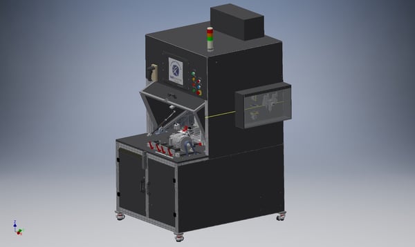
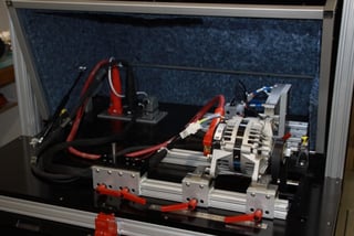
The team worked with the customer to select agreeable COTS hardware that was not only easy to repair and replace, but also durable. The tester was designed with a universal mounting and fixturing system to enable quick product line changeover for the different DUT models. The team also designed the tester to be ergonomically optimized to ensure operator ease of use and to minimize the potential for operator fatigue or injury.
The Ball Systems procurement team worked closely with the design engineers to ensure all the materials purchased met the durability and reliability requirements of the test system. Our production team built the tester based off our custom engineering team’s designs leveraging decades of experience in building both custom and build-to-print test systems utilizing our proven build-to-print processes.
With a multidisciplinary, complex system, there are often multiple significant engineering challenges that need to be resolved. A risk analysis is completed to determine key technical challenges that will require significant research or invention as part of the Ball Systems gated product development process. These risks are planned into the project timeline to not impact schedule or budget adversely.
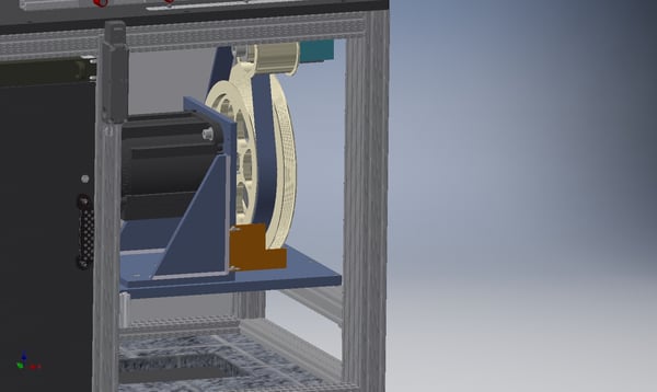
The specification required that the alternators be spun up to 18,000 RPM but also as low as 1,000 RPM with only one common drive motor. To accomplish this requirement, a gearing and pulley system was designed to allow effective transfer of speed and torque across the array of DUTs. There were a few complications with the types of pulleys required to meet the needs of all alternator models. The Ball Systems mechanical engineering team optimized the system through the design of three custom steel pulleys which were fabricated and balanced for optimal operation across all DUTs. The technician is now able to quickly change over the tester with a simple belt change and pulley selection.
During the build phase of the tester, it was observed that when the drive motor was enabled, a significant level of injected noise was observed in the 40 MHz range (due to the fundamental switching frequency and harmonics of the current in the power devices of the VFD). This noise injection was pervasive. The Ball Systems electrical engineers used their expertise in system level integration, noise control and data sampling to create a sub-VI that successfully filtered out the noise. They identified the noise using an oscilloscope. Then to determine the frequency content, they had to take a sample of the noise and perform a Fast Fourier Transform (FFT) on that signal. What that does is resolve that analog signal into its component frequencies. The team found the peak noise level at 40 MHz. Once the component levels where known, a filter that is tuned correctly to reduce the amplitude of the “problem frequency” could be created. The software engineers were then able to integrate this filter into the larger system using the sub-VI technique and built-in filtering tools from NI LabVIEW. The sub-VI successfully filtered the noise which allowed more accurate measurement of the signals from the alternator including the ripple current.
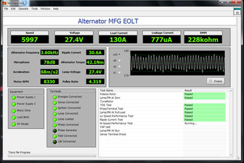
During the test, an alternator is tested by spinning up the DUT to multiple different speeds and then measuring output power. A pass or fail is determined depending on whether those values are within an acceptable range. On a modern alternator manufacturing production line, multiple aspects of the alternator’s performance are verified including electrical, mechanical, safety, sound, vibration, and even modern automotive or aerospace communication buses such as LIN or CAN.
Key Features of the Alternator Tester:


