+1 (317) 804-2330 | info@ballsystems.com | Blog

To develop a fuel injector measurement system for a Hardware-In-the-Loop (HIL) ECU test system that measures individual cylinder fuel injector driver characteristics and performs real-time waveform analysis and capture, allowing test engineers to “close the loop” on fueling delivered to an engine.
Ball Systems developed an injector measurement system as part of a compact, customized, and highly integrated desktop PXI-based measurement system with a full suite of custom software tools to perform software validation testing and analysis on engine control units (ECUs). The core of the test system hardware consists of an NI PXI chassis containing a real time controller running NI’s VeriStand engine, an NI R-series FPGA module, a high-current fault insertion system, and deterministically timed analog I/O to simulate sensors, actuators and other engine functions. The system’s software is based on NI’s VeriStand platform augmented with Ball Systems-developed custom devices, FPGA code and tools.
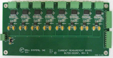
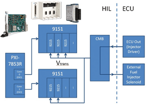
The injector waveform measurement hardware consists of an NI PXI 7853-R FPGA module connected to two NI 9151 4-slot expansion chassis which house a total of five 4-channel 9215 analog input cards. These cards are in turn connected to a series of Ball Systems current measurement boards (CMBs). These CMBs are based on linear Hall-Effect sensors which provide the benefit of inherent isolation from the system under test. With this set of hardware, the system is able to simultaneously sample 20 channels of injector current waveforms up to 12.5 A at 100 kS/s.
Ball Systems custom FPGA code then uses this hardware system to measure multiple parameters of each of the up to 20 fuel injector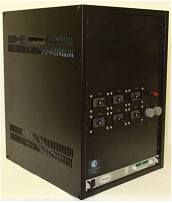 channels under test. Parameters measured include timing characteristics of injector pulses such as pulse duration, (which in turn is directly proportional to the volume of fuel delivered to the engine), and peak current levels. By directly measuring injector waveform duration, test engineers can “close the loop”, using fueling data on an individual cylinder basis in real time as inputs to their engine model. Since the code for performing these injector measurements is running on the same FPGA hardware as the engine simulation code that generates cam and crank timing signals, injector timing information can be measured with respect to absolute crankshaft angle. This information is useful when evaluating injector firing order and testing injector timing.
The software system also includes a VeriStand custom device to provide a deeper level of integration and functionality to the end user. In addition to performing channel-by-channel calibration from transducer voltage to actual injector current, the custom device allows the user to define parameter values on an engine-by-engine basis that are required for performing further calculations, such as current thresholds, timing offsets and expected firing order. These parameters are stored in user-defined XML files that can be used to rapidly switch between engine platforms. The custom device also performs conversion of injector waveform duration units from crankshaft angle to actual time units (microseconds) by monitoring the current engine speed of the engine simulation FPGA code. By presenting the duration in terms of time instead of angle, the custom device thus enables easier conversion to actual fuel delivered by the injectors which can in turn be used as an input to engine models running in VeriStand. A separate waveform viewer tool is also provided as part of the software system to allow further visualization and diagnosis by the test engineer.
Features:
Benefits:
Hardware:
Ball Systems maintains an expansive array of in-house equipment and immediately available platforms; reducing development time to meet critical customer deadlines. Specific components leveraged in developing the solution above included:


