+1 (317) 804-2330 | info@ballsystems.com | Blog

A tier-1 automotive supplier required the design and delivery of multiple dynamometer-based durability test stations for newly designed motor generators targeting the P0 hybrid electric vehicle (HEV) market.
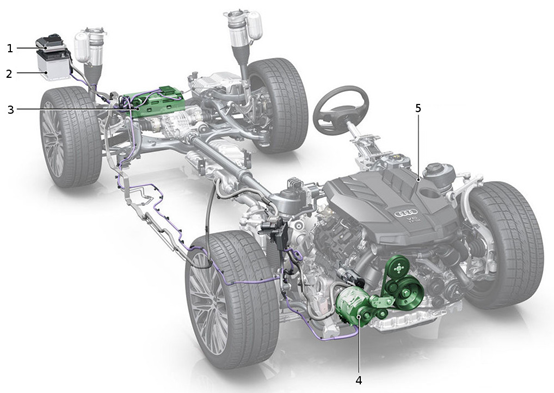
Credit: Audi
Diagram 1 –
1. DC/DC Converter; 2. Low Voltage Battery (12V); 3. High voltage battery (48V); 4. 48V belt integrated starter generator (BiSG). In a BiSG HEV architecture, the internal combustion engine (ICE) and the electric machine cannot be separated, they are mechanically linked through the front-end accessory belt (FEAD); 5. 3.0 TFSI internal combustion engine
Ball Systems designed, built, and validated six independent and universal belt-driven dynamometer-based durability test stations for motor generators utilizing Commercial Off the Shelf (COTS) subsystems, custom mechanical fixturing, industrial mechatronics/electronics, and network-based, open architecture National Instruments LabVIEW and LabVIEW Real-Time software.
The hybrid electric vehicle market has grown due to increased consumer demand, fuel efficiency improvements, environmental impact, and stricter vehicle emission policies worldwide. Current HEV architectures, referred to as P0-P4, are defined by the position of the electric machine and the type of connection with the powertrain or drivetrain (belt, integrated or gear mesh).
One of the most popular HEV architectures is the P0 configuration because it is the most cost effective due to the limited impact of the 48V system on the existing vehicle design. In a P0 HEV architecture, the electric drive is connected to the internal combustion engine (ICE) by a belt on the front-end accessory drive (FEAD). Though the P0 HEV architecture is easy to integrate into an existing vehicle design, the integration does not come without some significant engineering challenges.
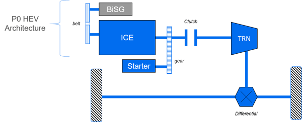
Diagram 2 – Illustrates the HEV P0 architecture, where the electric machine or the BiSG is connected to the internal combustion engine (ICE) through a belt, on the front-end accessory drive (FEAD).
The customer is a multi-national, tier-1 automotive supplier. They produce components for the industry including motor generators for P0 hybrid electric vehicles. The customer’s engineering team developed a new motor generator product for P0 HEVs and needed to have accelerated lifecycle testers designed and built. The motor generators being tested are a new technology family for this supplier and created multiple new technology challenges for them.
Ball Systems was carefully chosen to become an extension of the customer’s team to facilitate the completion of six durability test stations. The choice was made because of the following:
Despite the large physical footprint of the systems, heavy electrical requirements, and the need for a heating and cooling system utilizing CO2, we were able to effectively address the varied needs and challenges of the project. Our approach to this project was also more cost effective for our customer than the competition.
The hybrid electric vehicle motor generator test system designed is scalable to address new models across a wide array of testing requirements and future HEV rotating electric devices. As with most of our customers, the source code and other source design documents and files are delivered with the systems, so the customer's team can modify the test system functionality and sequences in the future, as needed.
In addition to the implementation of an open, scalable software architecture using LabVIEW and LabVIEW Real-Time, a structurally rigid frame and custom fixturing system for the device under test (DUT) were designed, built and validated. The system has a high-performance drive train supporting four-quadrant, motoring and generating in both rotational directions, and capable of consistent operation at multiple extreme conditions including parameters such as maximum torque, maximum acceleration/deceleration, high RPM, high temperature, low temperature, electronic loads, etc. The unique aspect of this drive train is its multi-bearing spindle shaft system positioned between the DUT and the load motor. Its purpose is not only to couple shaft rotation and torque from the drive motor to the DUT and vice-versa, but also to serve as a sacrificial wear component to minimize costly drive motor rebuild events due to the severe DUT durability test cycles implemented by the test system.
The engineering challenges that this test system addresses are:
1. Support four-quadrant (torque/speed) dynamometer operation in the 80-100 horsepower range
2. Simulate extreme automotive engine compartment thermal and electrical conditions
3. Provide a configurable test profile (recipe) generation capability with robust data collection and reporting
4. Provide an automated belt tensioning system with hub load measurement capability
5. Provide a commercially supported standard software environment
6. Utilize as many COTS components as possible
7. Provide an interchangeable fixturing system for multiple DUT mechanical designs
8. Provide a structurally rigid frame to maintain drive pulley, drive belt, and DUT pulley alignment
9. Adhere to customer specified safety and installation requirements
During the test the DUT is fixtured in a thermal chamber, a belt is then attached between the DUT motor pulley and the drive train pulley via a structurally robust, but still programmatically automated belt tensioning system. Rotation of the connected shafts is established by electrically powering the DUT motor from the DUT inverter or electrically powering the drive motor via the drive motor inverter. Power is transferred from the DUT motor to the drive motor via the drive belt or vice-versa depending on which motor is being electrically powered. Concurrently, the drive motor is absorbing power via the drive belt and transferring it back to the power grid via the drive motor inverter or in the case of the DUT motor absorbing power, via the DUT inverter back to the power grid through the battery simulator. The NI cRIO-based control system manages all the system level device operations and collects DUT and system data during test sequence execution.
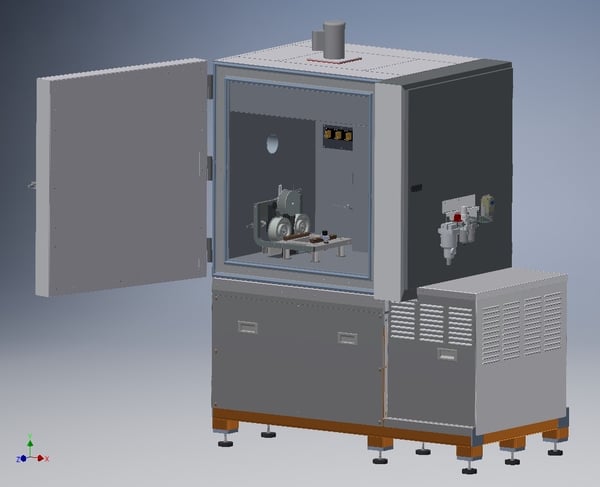
Image 1: CAD drawing of the thermal chamber and DUT mount fixture.
In a first-of-its-kind tester there are often technical and mechanical challenges that engineers must overcome to deliver the best solutions to their customer. With our specific expertise in rotating electrics, our team faced these challenges with the knowledge we have gained from similar projects. Two specific challenges that our team have overcome in this project were:
1. Creating an easy to use recipe generation system that was application specific yet extensible to new product classifications.
2. Designing a belt tensioning system with programmable tensions from 0 to 800 pounds coupled to a drive system capable of supporting a wide range of DUT pulley diameters and poly-V-belt configurations.
Software Recipes are Key to Durability Test Stations
Most of the test systems our team delivers using LabVIEW include test step sequencing functionality. This allows the end user to create test sequences by compiling a list of actions with defined parameters at each step. For example:
1. Set Power Supply: 24V with a 0.5A current limit
2. Set Relay Position: CR121 closed
3. Read Voltage: voltage must be between 11.5 – 12.5V to pass
In this instance, the customer intends to create tests that could run for weeks at a time, so their sequence would consist of thousands of steps if implemented discretely. To modularize sections of these lengthy test sequences, we added the ability to call sub-sequences within a test sequence, as well as the ability to iterate these subsequences any number of times. This is a common technique in software engineering but is not widely available in a test system programming environment, such as the test system being described here.
To illustrate this, let’s say for example that a test sequence involved setting a voltage, and then ramping a motor speed up and down a hundred times before shutting the voltage off. Initially, that would look something like this:
1. Set Power Supply: 24V with a 0.5A current limit
2. Set Motor Speed: 5000 RPM at 1000 RPM/s
3. Set Motor Speed: 0 RPM at 1000 RPM/s
4. Set Motor Speed: 5000 RPM at 1000 RPM/s
5. Set Motor Speed: 0 RPM at 1000 RPM/s
.
.
.
200. Set Motor Speed: 5000 RPM at 1000 RPM/s
201. Set Motor Speed: 0 RPM at 1000 RPM/s
202. Set Power Supply: Off
To simplify this however, we have two separate sequence files.
Sequence File 1: Motor Ramp
1. Set Motor Speed: 5000 RPM at 1000 RPM/s
2. Set Motor Speed: 0 RPM at 1000 RPM/s
Sequence File 2: High Level Motor Ramping Test
1. Set Power Supply: 24V with a 0.5A current limitInstead of having to write 202 separate action steps, our software engineers implemented this approach that allows the user to accomplish the same test sequence in only five steps. This modular feature saves the end user time when creating and modifying test sequences. These recipes can then be saved for future use, or for modification and easy creation of new recipes.
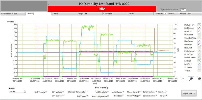
Image 2: LabVIEW GUI
Belt Tensioning System Imperative to Accurate Testing in Durability Testers
A key capability of the test system is the dynamic belt tensioning sub-system that enables the belt-assisted torque/speed linkage between the DUT and the drive train. It must maintain a programmable yet constant belt tension during any given test sequence.
The belt tensioning sub-system is based on a movable fixture assembly supported by four sleeve bearing-mounted sliding shafts. The tensioning system can produce programmable DUT hub load forces from 0 to 800 pounds. Actual force (hubload) measurements are taken directly from the load cell in real-time and belt breakage detection is supported and acted upon.
The bearings are bolted to a stationary table top and the fixture shafts are raised and lowered by a lower base plate. The tensioning force is provided by an air cylinder attached to a load cell mounted to the lower base plate on the bottom and threaded into the upper deck assembly on the top. The air cylinder actuation provides the benefit of accurate and constant belt tension independent of belt stretch during operation.
Two of the more difficult challenges associated with the tensioner development were:
1. Calibration of the air actuator and system output to account for the weight of the DUT fixturing and the DUT itself. Calibration was achieved using “certified dead-weights” loaded onto the fixturing system and mapping system hubload output data against actual applied deadweight.
2. Achieving accurate detection and reporting of belt slippage during real-time operation of the DUT and drive train. Belt slippage is a non-linear function of DUT hubload and DUT hub torque. Belt slippage affects drive belt useful life during testing and impacts DUT bearing life projections. We identified the linear operating regions of the belt slippage function and mapped them against measured hubload to establish a set of parametric functions for system operation. Our current useful operating range is: 200 pounds to 800 pounds hubload, 10 to 60 newton-meters hub torque and one percent to six percent belt slippage.
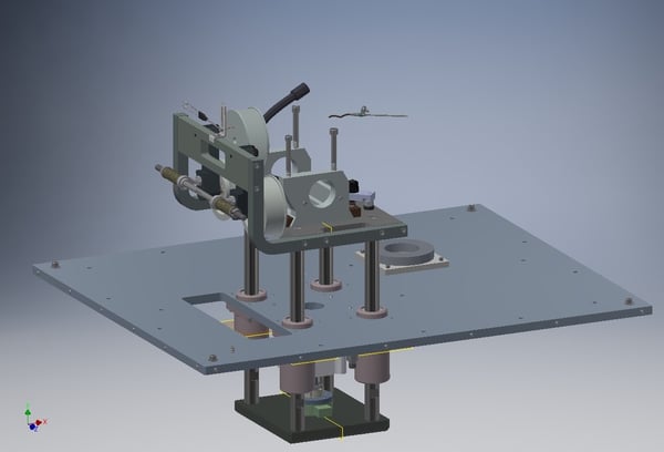 Image 3: CAD drawing of belt tensioning system
Measurements – Multiple measurements are monitored and recorded in real-time under extreme environmental conditions, such as temperature, that are rapidly cycling from one extreme to the other repeatedly and for a typical cycle of two weeks. The system may be required to complete six to eight cycles for one product.
Software
Hardware