
Not every piece of test equipment is a full rack of automated instrumentation. Sometimes what an aerospace maintenance team needs is something simpler and more direct: a manually operated monitor panel that lets a technician tap into a circuit, flip a switch, and read a live signal on the spot. No software, no startup sequence, just a reliable panel that works every time it's needed.
That was the brief behind this project: build a self-contained monitor assembly, from a customer-supplied mechanical, electrical, and acceptance-test package, that could be dropped into a larger ground support equipment (GSE) system.
|
|
|
This was a full build-to-print job, executed against a complete customer engineering package, including schematic diagrams, a wiring diagram, and a formal acceptance test procedure (ATP) that every unit must pass before it ships.
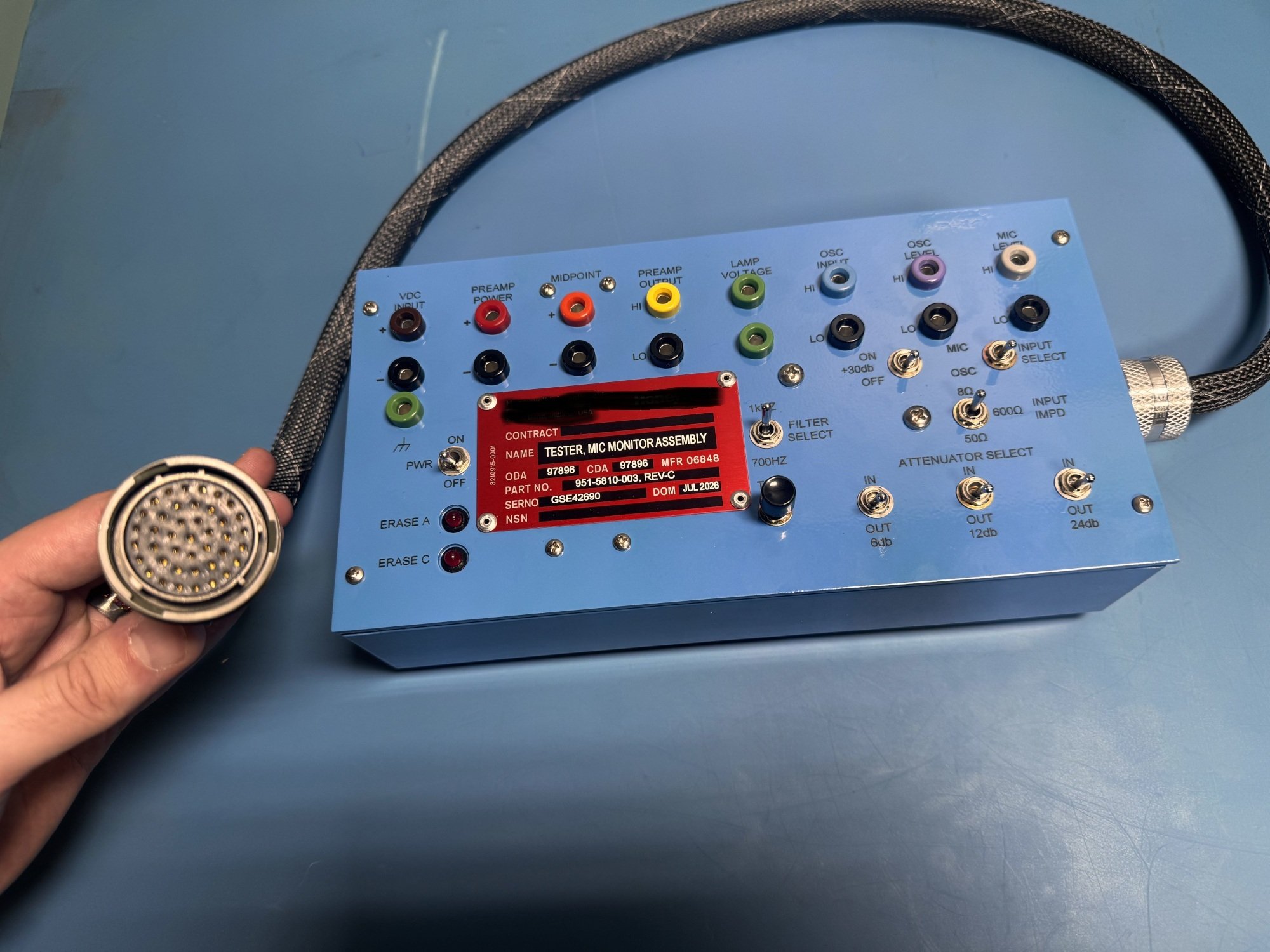
Machined and finished enclosure. The front panel is precision-cut, with identification markings lasered and backfilled for a durable, legible finish that won't wear off in the field. It is mounted to a purpose-built chassis sized to house the internal electronics.
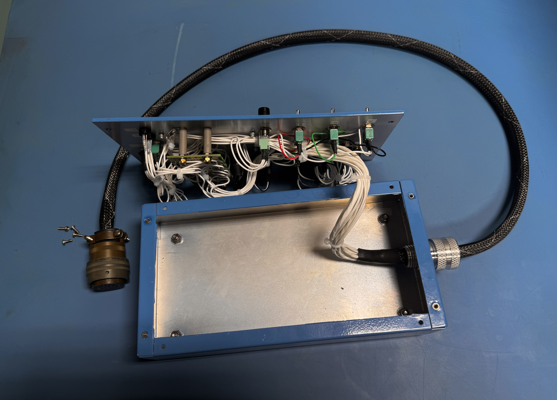
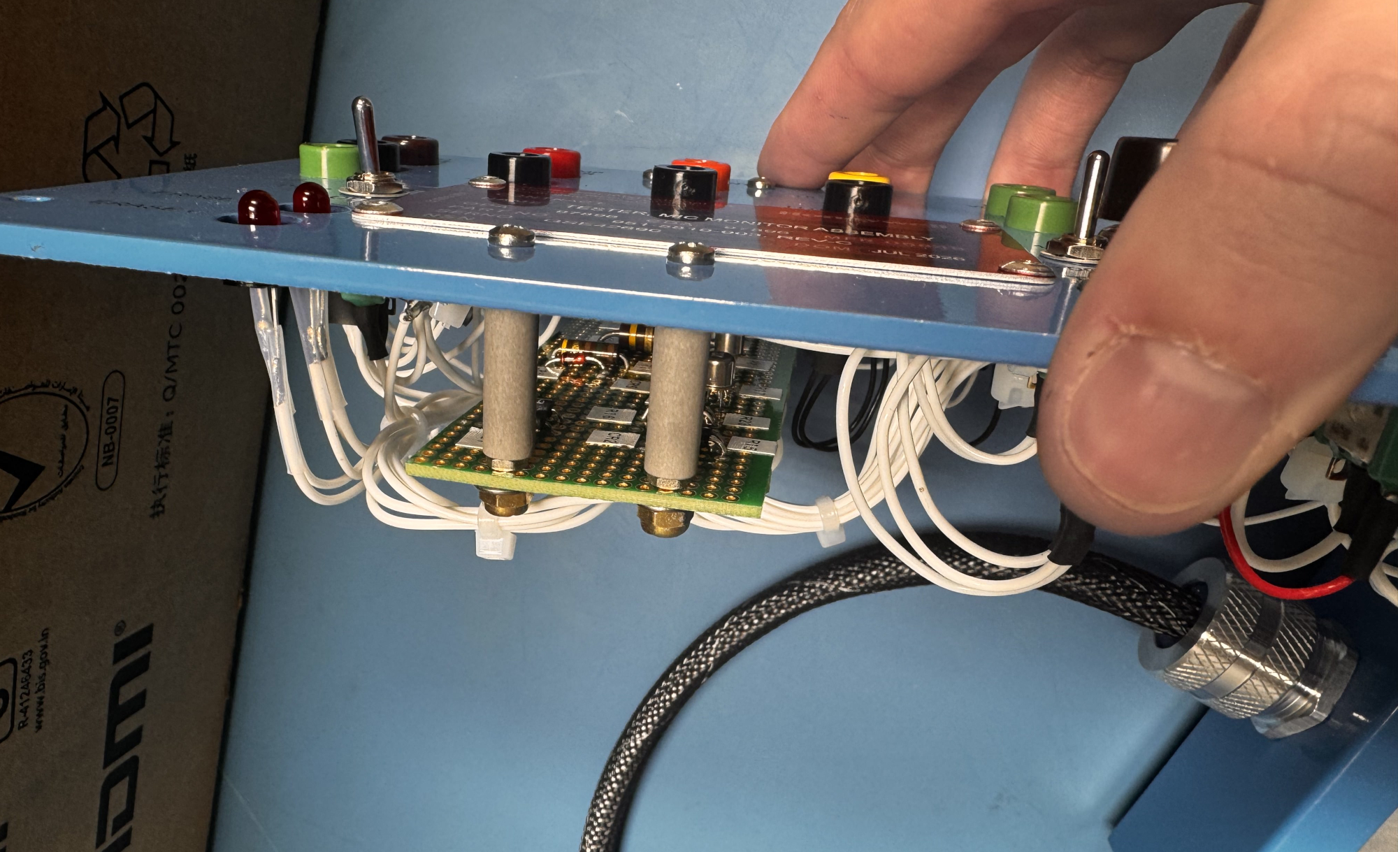
Custom PCB integration. At the heart of the assembly is a custom printed circuit board assembly (PCBA), built and tested to the customer's design, that handles the internal signal routing and conditioning for the panel's front-facing controls and indicators.
Operator-facing controls. The panel face is populated with a full set of color-coded banana jacks and binding posts for quick, tool-free test point access, along with panel-mount toggle and pushbutton switches and LED status indicators — giving a technician an intuitive, at-a-glance interface for monitoring circuit conditions.
Aerospace-grade internal wiring. Internally, the unit is wired with Teflon-insulated, mil-spec hookup wire (built to M16878/4 requirements) and shielded multi-conductor cable, dressed and secured with mil-spec-equivalent cable ties and lacing hardware — the same wiring discipline we apply to full test system builds.
Full traceability and sign-off. Every fastener, wire gauge, and substitute part used during the build is documented and cross-referenced back to the customer's bill of materials, with engineering approval on record for any substitutions made due to obsolete components — a common reality when building to a print that's been in service for years.
This project is a good example of what "build-to-print" really means at Ball Systems: it's not just populating a parts list; it's actively managing a program, including sourcing obsolete components, proposing and documenting customer-approved substitutions, and machining, wiring, and testing a finished assembly that has to perform flawlessly in a maintenance environment.

Ball Systems creates, develops, and delivers custom test systems and produces comprehensive build-to-print systems for companies that craft or manufacture critical electronic or electromechanical components for aerospace and defense, automotive, and consumer appliance applications.