

The term Ground Loop is often thrown into design literature as a placeholder for any circuit that causes ground noise.
In truth, a Ground Loop is one of many electrical design issues that may induce or reinforce existing ground noise. In both printed circuit boards and wired systems, a Ground Loop is, by definition, any complete circuit of low impedance grounding. This can be obvious, as with a ground plane with an air gap inside:

Figure 1: Ground Loop in a Copper Plane.
This phenomenon can also be more abstract, as in communication circuitry:
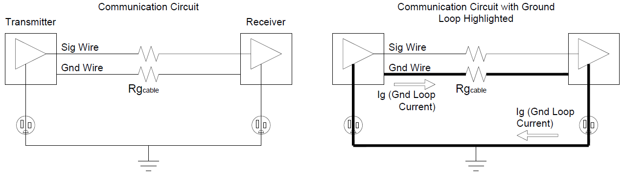
Figure 2: Communication Circuit (left) with its Ground Loop highlighted (right)
Ground Loops are typically problematic due to one of three events:
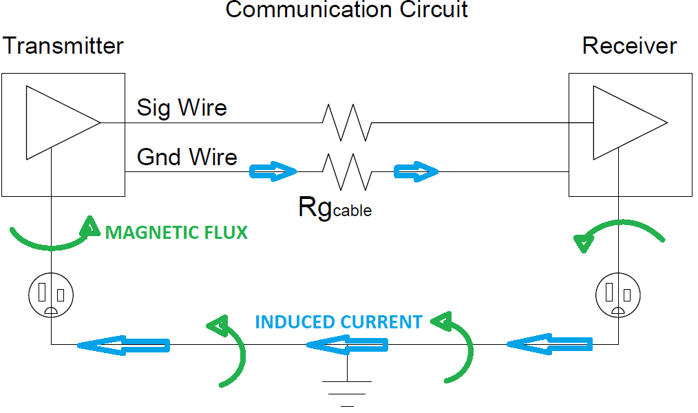
Figure 3: Magnetic Flux-Induced Current.
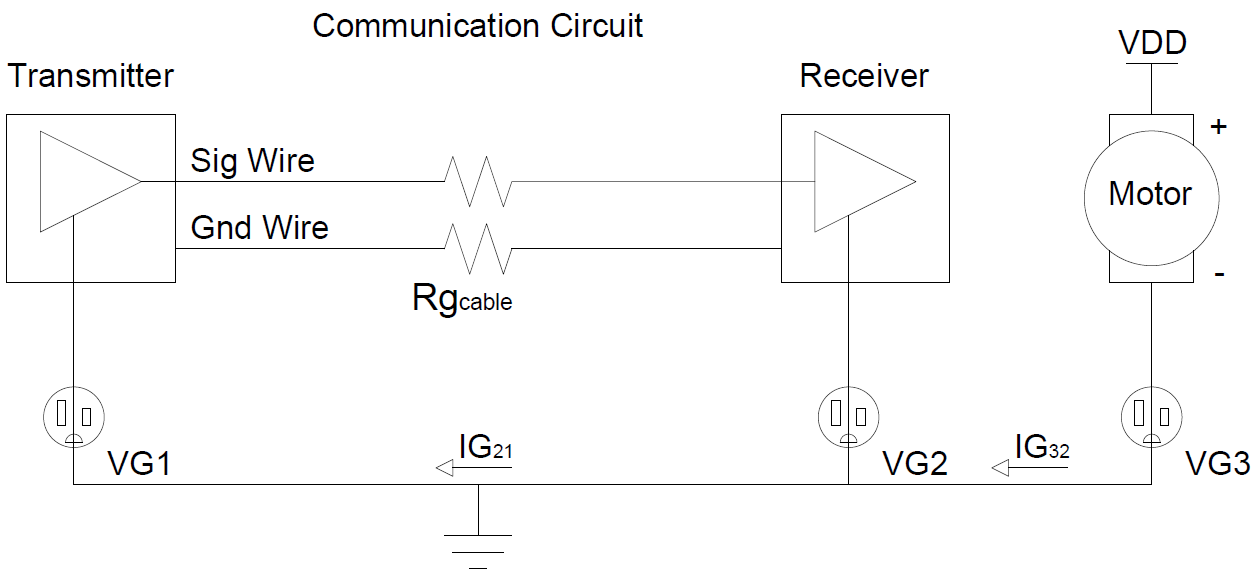
Figure 4: Multiple Ground Reference Current.
It’s important to remember that ground noise can exist without a Ground Loop present. For example, an External Circuit can produce ground noise on its own:
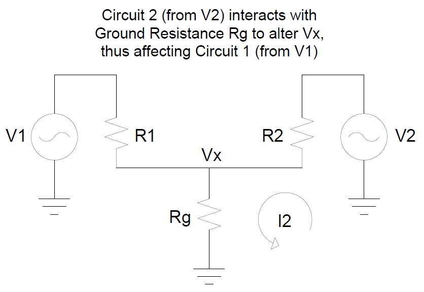
Figure 5: Ground Noise from an External Circuit.
At Ball Systems, we tend to utilize the following three methods for eliminating noise due to Ground Loops. These methods are an industry standard for cost-effectiveness and reliability.

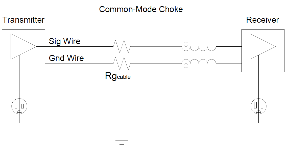
Figure 8: Common-Mode Choke.
There are multiple ways to eliminate Ground Loops, but attention must be paid not to sacrifice safety by breaking any necessary grounded connections. Multiple options are available to balance space availability, cost, and effectiveness, and it’s important to settle where on this triangle your interests are focused.
If you are interested in working with us on your next project, contact us at (317) 804-2330.

Ball Systems creates, develops, and delivers custom test systems and produces comprehensive build-to-print systems for companies that craft or manufacture critical electronic or electromechanical components for aerospace and defense, automotive, and consumer appliance applications.


Blog Comments