

Load cells are a critical component of many measurement, monitoring, and data acquisition systems in industrial applications. Load cells are relatively simple transducer devices which, when properly applied and instrumented, can provide highly repeatable indications of load/force across a wide range of applications and industries. Once configured and calibrated, load cells typically do not require routine maintenance and will provide accurate information over long periods of time. Load cells themselves usually generate only small analog signals, and these small signals must be amplified to meaningful levels to provide useful information to a measurement system. The focus of this article will be the configuration and calibration of the required load cell conditioning amplifiers.
Strain gauge load cell mechanics
A common type of electrically interfaced load cell is the strain gauge load cell. These load cells come in a variety of configurations, but all rely on basic yet fundamental electronic properties. In short, a load cell operates by detecting minute differences in the physical properties of an elastic medium as it is placed under mechanical stress. These mechanical stresses, generally compression or tension, cause very minute changes to the shape of the elastic medium, usually metal formed into a specific shape. While this article will not go into great detail regarding the many types of load cells, all share a common attribute - - their outputs must be conditioned properly and calibrated correctly to provide meaningful data to a measurement system.
Strain gauge load cell circuitry
Basic operation of a strain gauge load cell is as follows. A strain gauge is basically structured physically as a precision resistive array, known electrically as a “4-node bridge configuration”. Two input nodes of the resistive array are excited with a very precise voltage. The resistive array is also connected and its voltage output monitored across the remaining two signal nodes. Further, the resistive array is constructed such that the voltage across the signal nodes is zero under a no-load condition (i.e. no stress on the elastic medium). When a force is applied to the load cell the physical properties of the resistive array change, but only slightly. This slight resistive change results in a corresponding voltage change across the signal nodes, but again just a small amount. This voltage change is directly proportional to the force being applied to the load cell. To make the load cell useful, we must accurately measure this small voltage deviation.
Load cell configuration and setup
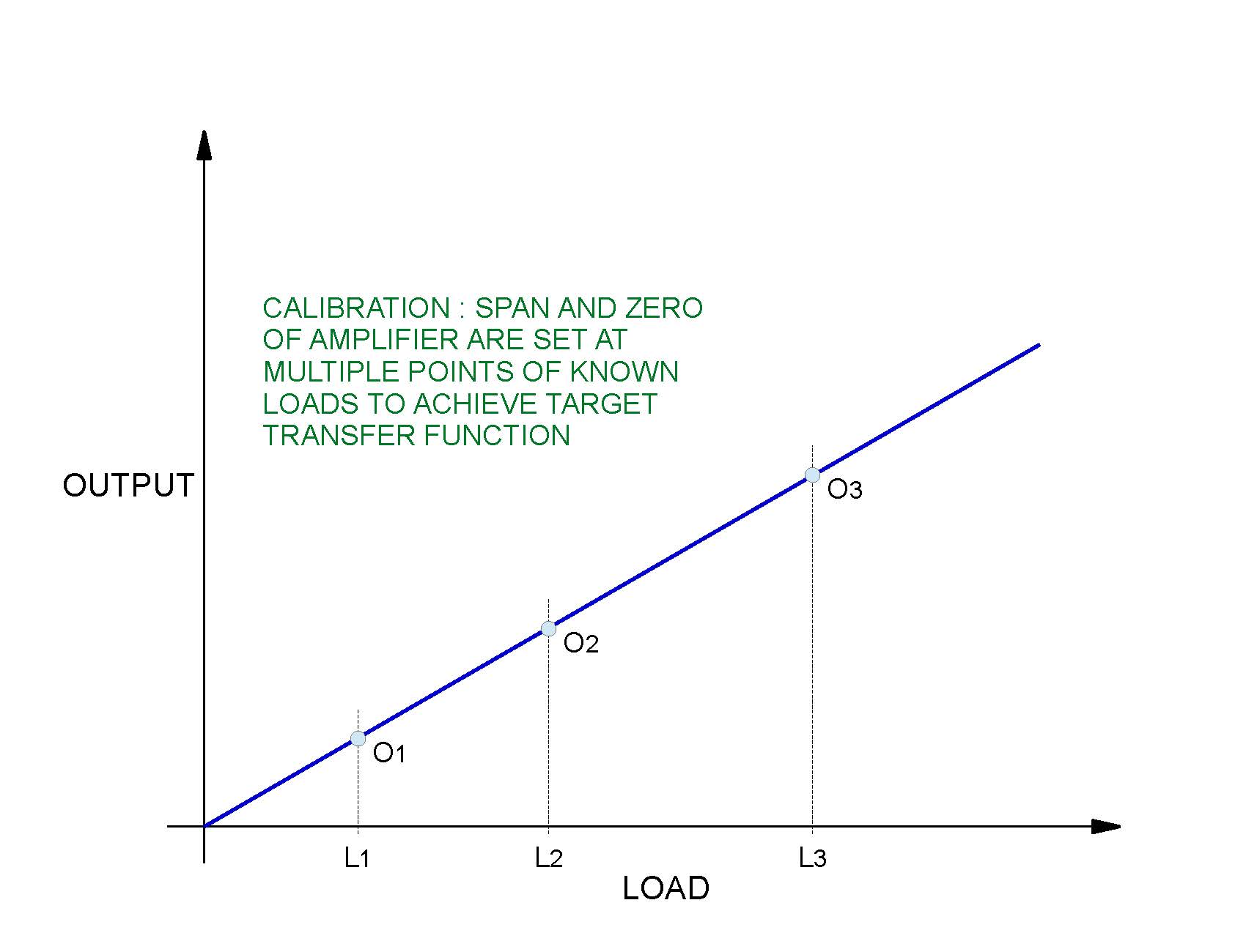
Arriving at meaningful measurement data requires careful initial configuration and setup of the load cell system. Load cells are constructed such that they generate a milli-Volt output signal based on the application of an excitation voltage several orders of magnitude larger. A load cell data sheet specifies this operational transfer function parameter as full range rated output in mV/V. A typical specified value for load cell rated output is 1mV/V. In addition, the data sheet will specify a maximum excitation voltage, which typically is 10VDC. Thus, the load cell in this example will generate a linear DC output signal from 0mV under no load condition to 10mV at full load condition. This low-level load cell output must now be converted to a voltage range that is more readily measured by the monitoring equipment in use. This is where the load cell conditioning amplifier becomes a crucial component of a load cell measurement system.
The conditioning amplifier input is connected to the output nodes of the resistive array. The conditioning amplifier translates the millivolt-level output signal of the load cell to a higher-level signal more readily readable by the measurement system. Typical output signal types of conditioning amplifiers are 4-20mA, 0-10V, and +/- 10V. Amplifiers have a multiplier capability, or gain, which is set to the desired value appropriate for the measurement system in use. Variable gain capability is provided via dip switches or a programmed setting using software. For example, an amplifier set to a gain of 1000 with a 0-10V output range connected to the strain gauge load cell from the previous paragraph would generate a 0V to 10V signal across its full range of operation. These voltage levels are easily monitored and acquired with common voltage measurement equipment.
Conditioning amplifier zero, span, and shunt
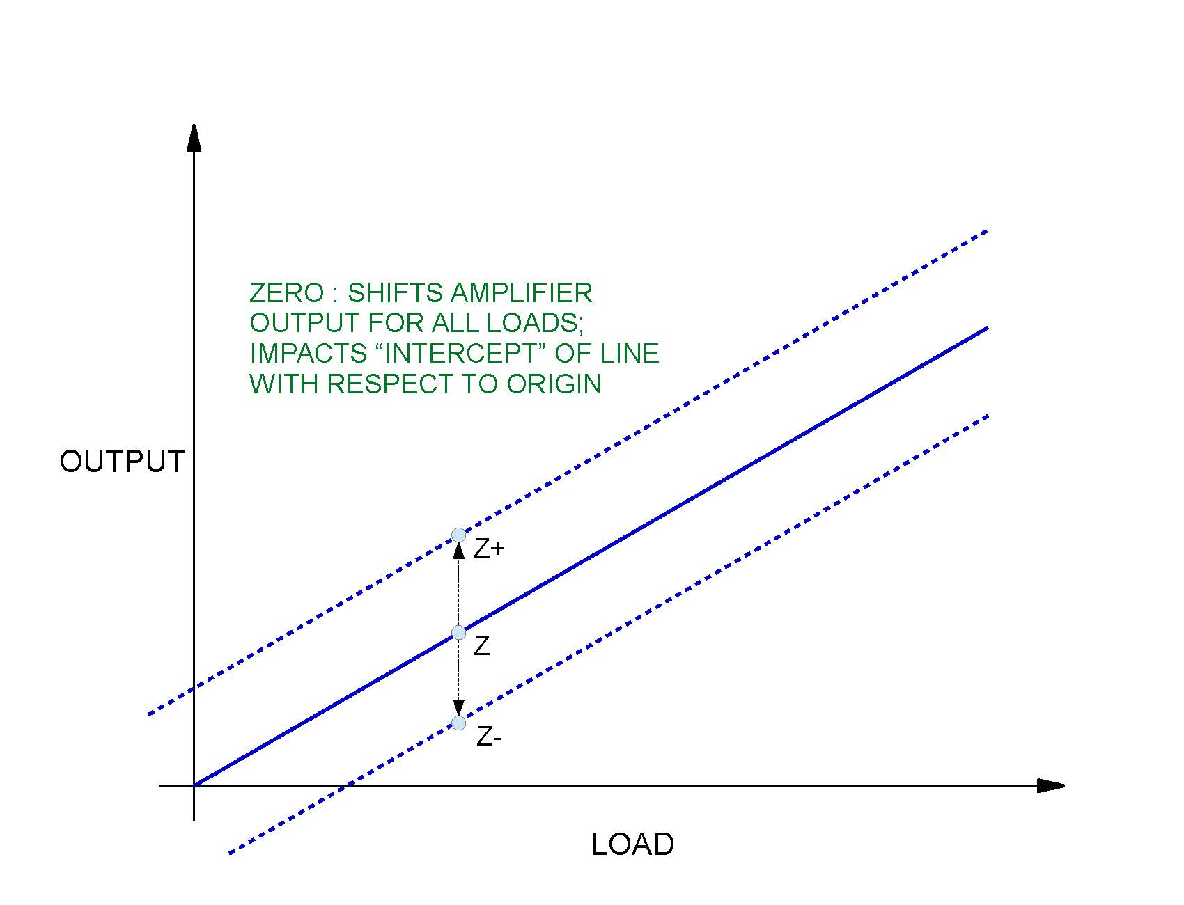
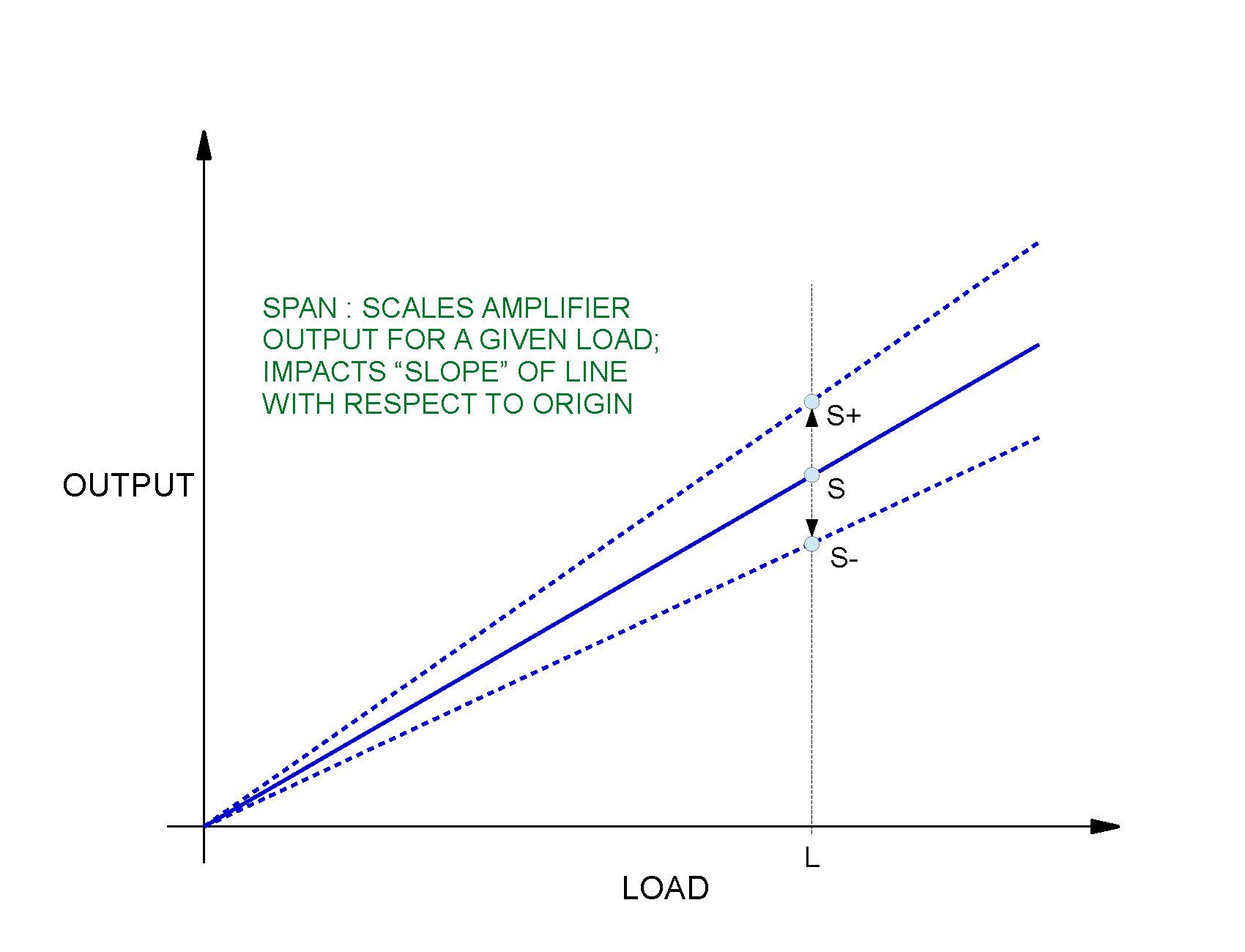
In addition to a gain setting, many amplifiers provide a method to adjust the offset and slope, often referred to as zero and span, of the amplifier gain function. This is often accomplished via miniature analog potentiometers on the amplifier, which provide a mechanism to fine tune the zero and span of the output signal.
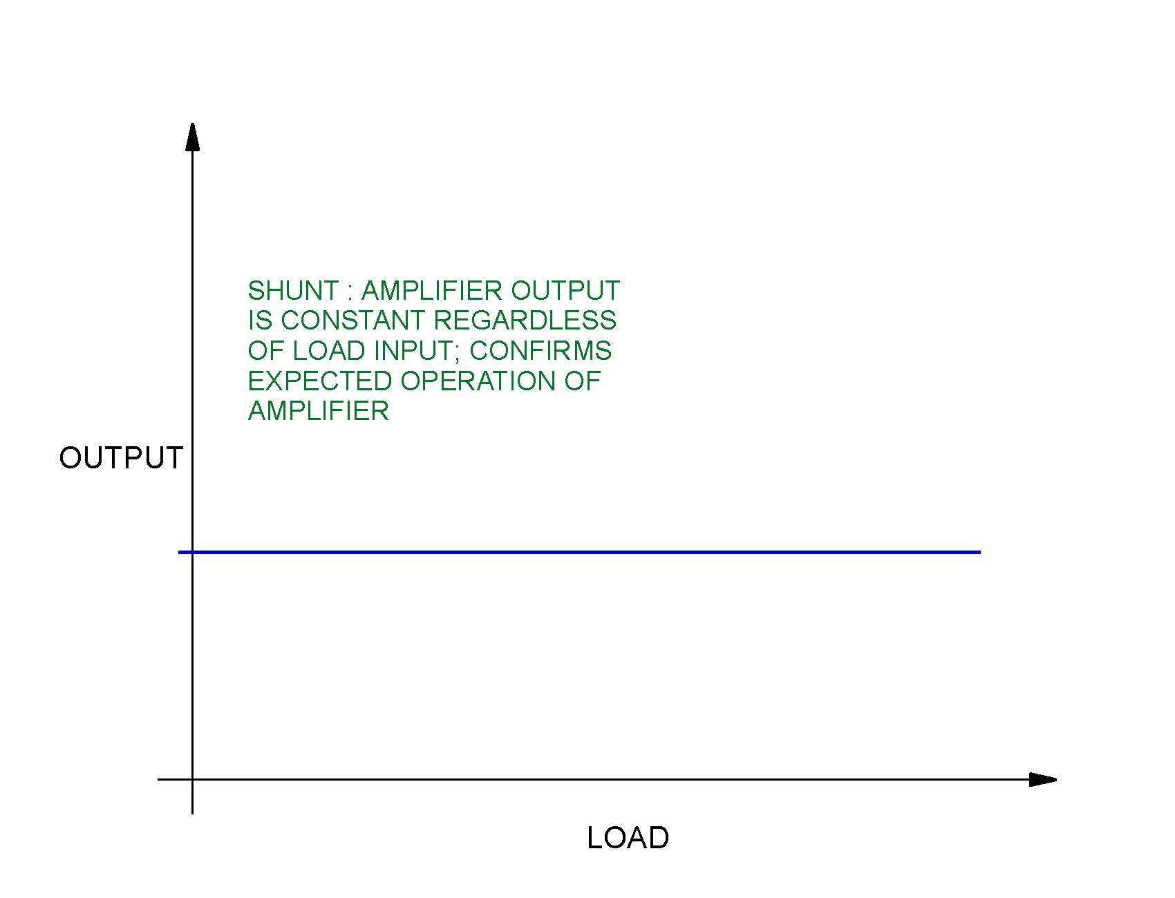
Additionally, conditioning amplifiers may be designed with a shunt capability to enable the amplifier to generate a preset value when the shunt is activated. This feature has the ability to check the operation of the conditioning amplifier at a known output value, allowing confirmation that system components and software are functioning properly or confirmation of “on” / “off” status of the conditioning amplifier.
Ball Systems is well versed in the use of load cells and conditioning amplifiers across a wide range of applications. We have implemented strain gauge load cells in torque control equipment, more traditional force monitoring applications, material and sub-component stress analysis, endurance testing and control, and other industrial equipment. For more information or to speak with an engineer regarding your load cell application, contact Ball Systems and we can design, implement, and deliver a custom solution to your unique situation.


Ball Systems creates, develops, and delivers custom test systems and produces comprehensive build-to-print systems for companies that craft or manufacture critical electronic or electromechanical components for aerospace and defense, automotive, and consumer appliance applications.


Blog Comments