

Updated July 2026
Functional test (FCT) is the pass/fail gate at the end of a printed circuit board assembly (PCBA) manufacturing line. After the board has been assembled, soldered, inspected, and — where applicable — in-circuit tested, FCT is the step that answers the only question that actually matters to the end customer: does this board do what it’s supposed to do when it’s powered up and exercised the way it will be in the field?
For general commercial electronics, that question can often be answered with a relatively simple go/no-go test. For aerospace and defense PCBAs — training boards used in fighter jet simulators, interface cards in avionics test stacks, control boards in ground support equipment — the answer has to be documented, traceable, and defensible to an auditor. The functional test strategy drives a lot of that.
This post walks through what functional test does, where it fits relative to other PCBA test methods, and what changes when FCT is applied to a build-to-print program for a regulated industry.
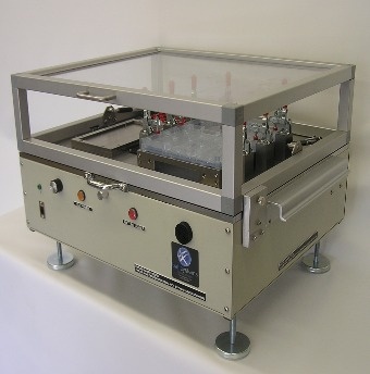
A complete PCBA test strategy usually involves multiple, complementary test methods. Each one catches a different class of defect:
FCT is the last of these in the sequence, and it’s the one that most closely approximates what the board will experience in its end application. Unlike ICT, which accesses the board at the node level through a bed-of-nails, FCT typically interfaces at the connector level — the same way the board will be connected in the field. That makes FCT fundamentally about behavior rather than structure.
A well-designed functional test exercises the board the way its end application will, checking things like:
A functional test that’s doing its job catches parametric failures (a component that’s in range at ICT but drifts under load), interaction failures (two subsystems that pass individually but fail when the board is fully powered), firmware anomalies, and assembly defects that made it past AOI and ICT. It will also, for most programs, log the measured values — not just pass/fail — so marginal units and trend drift can be caught before they become field failures.
Aerospace and defense PCBA programs carry test strategy requirements that go beyond what commercial boards typically need. A few differences worth naming:
Documentation and traceability. For programs operating under ITAR, AS9100 flow-downs, or DoD quality requirements, FCT data isn’t just internal process information. Measured values, serial-number-level test records, operator IDs, calibration status of the test equipment itself, and deviation documentation all become part of the board’s as-built record. First Article Inspection (FAI) reports and Certificates of Conformance depend on the FCT data package being complete and auditable.
Test equipment configuration control. The test system used to qualify an aerospace PCBA is itself part of the controlled process. Changes to the test sequence, instrument firmware, or fixture — even seemingly minor ones — can trigger a requalification. FCT platforms for A&D work are built with configuration control in mind: versioned test sequences, logged instrument firmware, calibrated and traceable measurement chains.
Obsolescence and legacy boards. A substantial portion of aerospace FCT work involves boards whose original test fixtures and test software are no longer supported by the original equipment manufacturer. Building a functional tester for a legacy PCBA often means reverse-engineering the original test intent from incomplete documentation, sourcing replacement instruments where the originals are obsolete, and validating that the new test produces results consistent with the historical acceptance criteria. This is common on legacy flight recorder test programs, fighter aircraft support equipment, and depot-level test stands.
Higher cost of field failure. A commercial PCBA that fails in the field causes an RMA. An avionics PCBA that fails in the field can ground an aircraft. The test plan is scoped accordingly — more thorough fault coverage, more margin testing, and more emphasis on catching parametric drift at FCT rather than letting it propagate.
Not sure whether your program needs a fully custom test strategy or a lighter-weight approach? Talk to one of our test engineers — no white paper required.
When Ball Systems manufactures a PCBA build-to-print, the customer owns the design and the test definition. Our job is to execute the assembly and test the customer specified , as opposed to not to redesigning the board or reinterpreting the test strategy. In practice, “execute the test” can mean any of the following, depending on what the drawing package includes:
All three paths are normal. The choice is driven by what the customer is trying to accomplish — pure contract manufacturing, delivery of both boards and test capability, or development of test infrastructure around an existing design.
A recurring pattern on PCBA programs with multiple variants is that each variant gets its own dedicated functional tester. Over time, that produces a line with six, eight, or a dozen similar-but-not-identical test stations — each one occupying floor space, each one requiring its own calibration schedule, each one requiring its own operator training.
A universal test platform consolidates that. One hardware platform, configurable through software and interchangeable fixtures, tests the full family of DUTs. When done correctly, the consolidation reduces floor space, operator count, and calibration overhead, and produces a test record format that’s consistent across the product line.
Done poorly, it produces a platform that technically supports every variant but does none of them well. The difference is whether the test requirements for every DUT in the family were available and analyzed before the platform architecture was frozen. If a customer is considering a universal approach, the preparatory work is providing the complete function list, test parameters, and acceptance criteria for every variant up front — not after the first variant is in production.
Ball Systems has built universal test platforms for both commercial and aerospace applications. The white paper linked below walks through the architecture and trade-offs in more detail.
Download Our White Paper: Universal Test System Design
Is functional test the same as in-circuit test?
No. ICT verifies individual components and net-level continuity using a bed-of-nails fixture, checking that the board was built correctly. FCT exercises the completed board through its normal interfaces to verify it behaves correctly — a board can pass ICT and still fail FCT if the components interact incorrectly once the whole system is powered up.
What’s the difference between functional testing and lifecycle testing?
Functional testing validates that a board performs correctly right now. Lifecycle testing (thermal cycling, durability, electrical and environmental stress) validates how the board holds up over time and under environmental extremes. Most PCBA programs use both — FCT at the end of the line, lifecycle testing as a separate qualification activity.
Do we need functional test if we already run in-circuit test?
In most cases, yes. ICT and FCT catch different failure classes. ICT is fast and catches manufacturing defects at the component level; it can’t catch interaction failures, firmware issues, or performance-under-load problems that only appear when the board runs as a system. Programs that skip FCT are relying on ICT to catch failure modes it wasn’t designed to find.
Can Ball Systems build a functional tester for a board with an obsolete original test system?
Yes — this is common work for us, particularly on legacy aerospace and defense programs where the original test fixture, instruments, or software are no longer supported. It typically involves reverse-engineering the original test intent, sourcing replacement instrumentation, and validating that the new tester’s results match the historical acceptance criteria.

Ball Systems creates, develops, and delivers custom test systems and produces comprehensive build-to-print systems for companies that craft or manufacture critical electronic or electromechanical components for aerospace and defense, automotive, and consumer appliance applications.




Blog Comments